Error as Form: Exploring the Aesthetic and Structural Potential of Deformation in Digital Fabrication
Abstract
Background While digital fabrication primarily focuses on precise replication, its potential for sculptural exploration through deformations remains largely underexplored. Recent studies suggest embracing technical glitches as creative elements, and this study builds upon that perspective. Introducing the Error-Driven Design Fabrication Workflow, this research integrates deformations as an active component of the design process rather than unintended flaws.
Methods To explore intentional deformations in 3D printing, this study examined three key variables: structural instability due to gravity, retraction effects, and curvature-induced deformation. The digital model was systematically adjusted, followed by an iterative printing process to observe and analyze the resulting deformation patterns. Rather than treating these distortions as mere errors, the study implemented an iterative reverse modeling feedback workflow, reframing unintended deviations as sculptural elements within the design process.
Results The experimental analysis reveals that deformations emerging during fabrication broaden the scope of sculptural exploration. Gravity-induced instability generates collapse patterns, introducing new possibilities for form development. Retraction effects disrupt filament connectivity, resulting in intricate, web-like textures that can be utilized as surface design elements. Increased curvature leads to layering instability, shaping distinct geometric patterns and influencing overall structural articulation.
Conclusions By shifting the perception of deformations from errors to design tools, this study presents an alternative fabrication approach that prioritizes sculptural exploration over rigid precision. Through iterative feedback, deformations are incorporated into the design process to expand formal possibilities. Future research will focus on real-time feedback integration and extend this approach across varied materials and fabrication techniques.
Keywords:
Error-driven Design, Digital Fabrication, Generative Deformation, Computational Workflow1. Introduction
Digital fabrication has focused on precision and repeatability, yet the sculptural potential of fabrication-induced deformations remains largely unexplored. Traditional computer-aided design (CAD) and computer-aided manufacturing (CAM) systems have prioritized efficiency and precision, often focusing on optimized production over creative inquiry (Cardoso Llach, 2015). Despite their advantages, these tools have limitations in capturing informal and subjective design elements in the creative process (Bazjanac, 1975).
Digital design often operates on a deterministic logic that prioritizes physical accuracy and total control, thereby relegating material responsiveness and contingency to a secondary role in the creative process.
In 3D printing, deviations such as retraction marks or sagging are usually minimized as flaws, although they can also generate sculptural possibilities. In this study, error is defined not as a malfunction but as a deliberate departure from standard production norms. Even predictable deviations—such as gravitational sagging—are reinterpreted here as productive catalysts intentionally integrated into the design process. Unlike precision-focused approaches, this study proposes the Error-Driven Design Process, which integrates deformations into sculptural exploration.
The Error-Driven Design Process treats deformation not as a defect but as an essential dialogue between digital intent and material behavior. Through iterative feedback, these deviations are refined into new sculptural forms.
This study focuses on three key research directions.
- 1) Intentional Error Design: In Geometric Processing, design parameters (thickness, spacing, curvature) are adjusted to induce controlled deformations.
- 2) Exploring Output Discrepancies: In Fabrication, deformations are recorded and analyzed as sculptural opportunities.
- 3) Iterative Feedback through Reverse Modeling: Deformation data is reverse modeled into digital parameters to generate new iterations.
Through this iterative process, the study moves beyond the precision-driven CAD-CAM paradigm, proposing a design methodology that employs deformations as creative tools. By reconsidering the discrepancies between digital modeling and material output, this study explores fabrication inconsistencies as sculptural experimentation to expand formal possibilities.
2. Related Work
2. 1. Theoretical Perspectives on Error in Design
In the process of design and making, error is often understood not as a failure, but as a moment where material agency and designer intention intersect—a point that reveals the creative potential inherent in digital fabrication. Rather than treating error as a flaw to be corrected, this perspective considers it a productive force that can shape design outcomes in unexpected ways.
Through his notion of the anti-aesthetic, Hal Foster (1983) challenges traditional ideas of beauty, favoring process and experiment over polished perfection. The glitch, described by Rosa Menkman (2011) as both destructive and generative, emerges as a rupture that opens space for new forms to take shape—an error that becomes a vital means of generating artistic meaning.
Drawing from new materialist thought, Jane Bennett (2010) reminds us that materials possess their own agency, refusing to simply yield to human intention and sometimes intervening or even transforming a designer’s plans. Tim Ingold (2013) also suggests that making is not a one-way act of imposition but an ongoing dialogue between human intention and the flows of materials and forces. These ideas resonate in the discourse of post-digital fabrication, which calls for a renewed appreciation of error, uncertainty, and the unruly nature of materials—an invitation to embrace the imperfect as part of the creative process.
2. 2. Comparative Case Analysis of Error Engagement
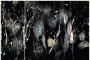
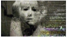
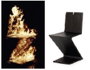
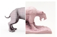
Depending on how the concept of error is framed, this section analyzes selected cases of creative work. Two criteria guide this analysis: (1) whether the error emerged naturally, and (2) to what extent the creator controlled or adjusted that error. These criteria distinguish between approaches that embrace error as a chance occurrence and those that structure it as a deliberate design variable. Table 1 classifies six cases based on the way error intervenes in the creative process. Each case illustrates how error is harnessed within the act of making, serving as a foundation for situating this study within its broader context.

Design Cases Classified by Error Involvement
The four cases at the top of the table (Saraceno, Menkman, Baas, and Alterfact) align with an approach that accepts error as an external factor or chance occurrence, interpreting it as an aesthetic or conceptual resource. These creators reveal errors in its raw form or incorporate traces of destruction and instability into their work.
By contrast, the two cases at the bottom (FreeD and Glitch Knitting) engage with error through detection or code-level modulation. They seek to tightly control the production process by limiting the scope of error or by deliberately inserting it, treating error as a repeatable and calculable element. While earlier studies have often focused on embracing error as an outcome or transforming unintended variations into aesthetic effects, attempts to partially control errors such as in FreeD and Glitch Knitting—have remained relatively limited. This study builds on those precedents yet also seeks to explore ways of configuring error as a repeatable condition, integrating it more deliberately into the design process.
3. Proposed Error-driven design Workflow
3. 1. Error-driven design Workflow
This study proposes an Error-Driven Workflow that considers deformations occurring during the digital fabrication process not as mere errors but as elements for exploring new forms. Unlike conventional CAD-CAM methods, it views errors as factors that expand sculptural possibilities. In other words, it embraces the uncertainties and deformations arising during fabrication and uses them as tools for design exploration.
The proposed workflow, as shown in Figure 1, consists of four main phases, each forming a nonlinear iterative process so that fabrication functions as a system that accounts for material responses rather than mere execution.

Error-Driven Design Process: An Iterative Feedback Loop Incorporating Reverse Modeling in Digital Fabrication
Phase1) Geometric Processing
Design variables are adjusted to anticipate deformations, generating a parametric model in Grasshopper. A controlled deformation factor is introduced to guide experimental exploration.
Phase2) Fabrication
The digital model is translated into G-code, with printing conditions set to induce specific deformations. Support structures are omitted, allowing material responses to shape the outcome. Iterative experiments adjust parameters to amplify deformations or explore new forms.
Phase3) Evaluation and Reverse Modeling
The printed result is compared to the digital model to interpret sculptural meaning. Scanning and measurement convert physical deviations into digital data, which are reintegrated as design variables—such as material response, structure, or texture—turning deformation into a design tool.
Phase4) Aesthetic Exploration
Iterative experiments analyze printed patterns to explore sculptural potential. Reverse Modeling integrates deformed forms into the design, enabling further manipulation for expanded formal exploration. Finally, the design applicability of deformations is evaluated, incorporating them as generative tools for form development.
3. 2. 3D Printing Errors and Experimental Variables
Various types of errors can occur in the 3D printing process. Based on previous research and case analysis, 3D printing errors have been broadly categorized into two groups, as shown in Table 2.
Classification of 3D Printing Errors (Adapted from Simplify3D, n.d.)
This study examines three deformation factors—independent of hardware issues—through experimental analysis, adjusting design and printing parameters as outlined in Table 3.
Experimental Variables and Design Considerations
3. 3. Evaluation Criteria for Aesthetic Utility
To make the assessment of deformation outcomes transparent and repeatable, this study adopts a theory-grounded rubric for aesthetic utility—the degree to which an induced deformation both (a) enriches perceptual qualities and (b) remains compatible with functional or structural intent. Table 4 summarises the three sub-criteria and the 0–5 scale used in this rubric.
Aesthetic Utility Evaluation Rubric
The three criteria are adapted from established discussions of unity–novelty balance and functional fit in product-aesthetics research (Hekkert, 2006; Veryzer & Hutchinson, 1998). In the exploratory phase reported here, scores were assigned internally by the authors to guide iterative tuning of print variables. A comprehensive expert-panel validation and inter-rater reliability analysis is planned for future work.
By specifying measurable sub-criteria and a common scale, the rubric constrains purely subjective judgements and provides a reproducible framework for comparing alternative parameter sets in subsequent studies.
4. Workflow Implementation
4. 1. Geometric Processing
In the first phase, a parametric digital model is created in Grasshopper, adjusting experimental variables to induce deformations. Figure 2 shows the Grasshopper node structure used in the experiment.

Parametric modeling in Grasshopper: (a) Gravity-Induced Instability, (b) Spacing Retraction, (c) Curvature-Induced Deformation
The overall structure remained unchanged, while specific parameters were adjusted to control output deformations. Each node group shown in Figure 2 played a critical role in adjusting the experimental variables, enabling an analysis of the influence of each variable on the output process.
4. 2. Fabrication
This phase entails converting the digital model into G-code and performing iterative experiments to induce deformations.
The output process cycles through three steps—Convert to G-code, Observed Deformation, and Modify & Reconfigure for Further Exploration—as illustrated in Figure 3.

Iterative workflow integrating errors as a design exploration tool.
To directly observe deformations, the Convert to G-code step is executed without support structures, ensuring that the printed object relies solely on its inherent structural stability. This setup allows deformations to emerge naturally through variable adjustments rather than being artificially constrained. Once printing is complete, the deformations are documented and analyzed in the Evaluation phase. The model is then modified and reconfigured to amplify specific patterns or generate new forms, followed by renewed digital modeling. Through these iterations, the deformation characteristics are systematically explored, enhancing their sculptural potential.
By continuously cycling between Fabrication, Geometric Processing, and Evaluation, this methodology transforms unpredictable deformations into deliberate opportunities for sculptural exploration.
4. 3. Evaluation and Reverse Modeling
This section evaluates the outcomes of the three primary experimental variables—thickness (structural stability under gravitational influence), spacing (filament retraction effects), and curvature (amplitude-induced deformation). Using a reverse modeling methodology, each variable was incrementally adjusted based on prior observations to achieve an optimal balance between structural integrity and aesthetic potential.
The evaluation process consists of:
- 1) Independent analysis of each variable to understand its influence on material behavior.
- 2) A comparative selection matrix to synthesize results and determine the most viable parametric conditions.
This experiment analyzes structural collapse and deformation under gravity, examining the potential of controlled deformations as sculptural elements. As shown in Figure 4, thickness was systematically varied at specific intervals to observe deformation patterns and structural limitations, with the goal of identifying an optimal thickness that balances stability and sculptural expressiveness.

Transformation of Structural Stability with Thickness Variation
The experiment showed that when thickness was reduced below 1.0mm (GR_T3), structural collapse occurred, compromising practicality. In contrast, GR_T6 (6.0mm) and GR_T2 (2.0mm) maintained stability while forming distinct sculptural patterns (Figure 4). Though both conditions provided similar stability, their pattern formation differed. GR_T6 created sharp deformation patterns, allowing for intricate expression, while GR_T2 exhibited minimal deformation but a uniform and refined pattern.
This suggests design applicability, providing criteria for selecting the appropriate thickness based on design objectives.
Meanwhile, GR_T1 (1.5mm) demonstrated high stability but lacked deformation, making it inconsistent with sculptural goals. This indicates that a stability-focused approach may limit sculptural diversity.
In conclusion, GR_T2 (2.0mm) and GR_T6 (6.0mm) balanced stability and sculptural potential, with their pattern differences suggesting diverse possibilities in sculptural design. These findings serve as a valuable reference for future design applications.
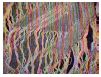
The experiment examines how filament spacing affects retraction patterns and sculptural properties, exploring their design potential. As shown in Figure 5, spacing was systematically adjusted to observe pattern formation and texture characteristics.

Transformation of Retraction Patterns with Spacing Variation
Retraction-induced web-like patterns were observed across all spacing conditions. At 1-2mm, dense patterns formed, resembling a continuous membrane, making the printed object appear flexible and elastic, suggesting potential for sculptural texture applications. As spacing increased, patterns became more fragmented and irregular. In RT_S6(15mm) and RT_S7(18mm), patterns appeared irregular, resembling unintended errors, yet these irregularities indicated potential for organic and natural textures. At 90mm or wider, pattern density decreased, and strands aligned linearly, exhibiting transparent layer-like characteristics.
Notably, in RT_S12(200mm) and RT_S13(500mm), weakly connected and directional structures emerged, suggesting potential applications in delicate sculptural elements and semi-transparent layering.
Narrower spacing resulted in denser and more flexible textures, whereas wider spacing produced weaker and more simplified structures.
These findings suggest that retraction patterns are not merely printing errors but can function as sculptural elements depending on spacing conditions. By adjusting spacing parameters according to design objectives, retraction patterns can be intentionally incorporated into sculptural design.
The relationship between curvature and deformation patterns was examined, focusing on its sculptural potential. As shown in Figure 6, Amplitude values were varied from 20 to 80, allowing an analysis of how curvature at specific points generates distinct textures.

Transformation of Curvature-Induced Deformations with Amplitude Variation
At Amplitude values of 20–30 (CU_C1, CU_C2), the prints maintained structural stability, while distinct textures emerged at curvature points. These textures exhibited delicate patterns unattainable through digital modeling, making them particularly effective for sculptural applications. Additionally, flat areas retained their original form, allowing for localized deformation to introduce unique design elements. As Amplitude increased to 40–60 (CU_C3, CU_C5), curvature effects became more pronounced, producing stronger textures between curved sections. However, these textures often appeared overly exaggerated or irregular, reducing their practical usability in sculptural design. At Amplitude values of 70–80 (CU_C6, CU_C7), excessive curvature compromised structural integrity, leading to form collapse. Under these conditions, textures became unstable and unbalanced, significantly limiting their applicability in sculptural contexts.
The findings indicate that Amplitude values between 20 and 30 (CU_C1, CU_C2) yielded the most effective balance of stability and textural refinement. In particular, CU_C1 (20) and CU_C2 (30) preserved structural integrity while generating intricate textures with high sculptural potential. In contrast, Amplitude values above 40 resulted in excessive deformation or structural failure, making them unsuitable for controlled sculptural applications.
4. 4. Aesthetic Exploration
The final stage of this study explores new sculptural possibilities by combining the results from the thickness, spacing, and curvature experiments. Based on the findings from Section 4.3, three variable combinations were selected to produce physical prints, extending beyond experimental analysis to investigate design applications.
As summarized in Figure 7, these combinations were chosen to balance structural stability, sculptural applicability, and controllability. Each combination exhibits distinct characteristics suited to different design objectives.

Aesthetic Exploration Matrix
Designed to emphasize organic and irregular patterns with delicate and fragile textures. While structural stability is relatively low, the result (Figure 8) features intricate, thread-like formations that enhance aesthetic value. This combination is suitable for artistic and experimental applications where visual complexity is prioritized over structural rigidity.

3D-printed structure of Combination 1
This setup generates a dense, crystalline texture, maximizing sculptural aesthetics. While its structural stability was moderate, the unique surface texture created dynamic interactions with light and shadow, producing sculptural expressions well-suited for artistic applications (Figure 9).

3D-printed structure of Combination 2
Achieving the best balance between stability, sculptural value, and controllability. The resulting print (Figure 10) combined refined patterns with smooth transitions, integrating structural and decorative elements, making it ideal for high-precision design applications.

3D-printed structure of Combination 3
5. Conclusion and Discussion
This study explored the potential of utilizing deformation as a sculptural element within the framework of the Error-Driven Design Process. By manipulating three key variables—thickness, filament spacing, and curvature—the experiments demonstrated that deformations caused during the fabrication process can serve as intentional design features rather than mere anomalies.
The results showed that structural collapse due to gravitational instability occurred below a certain threshold of thickness, while repetitive and organic patterns emerged under specific conditions. Filament retraction affected the density and texture of surfaces, and curvature-induced deformations created distinct surface patterns within a usable range, though excessive curvature decreased print stability.
Beyond single-variable tests, combinations of variables enabled more complex sculptural exploration. Patterns generated from these combinations were analyzed according to three criteria: structural stability, applicability to sculptural design, and controllability. Some combinations yielded stable yet organic textures, while others enhanced surface articulation and expressive potential.
Reverse modeling was also employed to reinterpret deformation not as a byproduct but as an integral part of the design process. This method enabled the generation of forms unattainable through conventional modeling approaches, allowing unpredictable outcomes to be reintroduced into the design workflow.
By critically addressing the deterministic logic of precision-focused digital design, this study offers an alternative framework that embraces uncertainty and deformation as essential components of creative form-making.
These findings suggest that as digital fabrication technologies continue to prioritize precision and repeatability, there is value in reframing error and deformation as opportunities for creative experimentation. The proposed approach demonstrates that digital fabrication can extend beyond replication toward sculptural inquiry through the intentional integration of error.
However, the experiments in this study were limited to Fused Deposition Modeling (FDM) and specific printing conditions. The deformation characteristics observed may vary significantly across other fabrication methods such as Stereolithography (SLA) or Selective Laser Sintering (SLS). Future research should explore alternative techniques to expand the scope of sculptural approaches and investigate new material interactions.
Additionally, while this study focused on three selected printing parameters, further investigation into factors such as nozzle diameter, filament material, layer speed, and printer type would help build a more comprehensive understanding of deformation phenomena. Continued research in this area will contribute to developing a systematic methodology for incorporating deformation as a controllable and repeatable element within design workflows.
Acknowledgments
This work was supported by Creative-Pioneering Researchers Program through Seoul National University.
Notes
Copyright : This is an Open Access article distributed under the terms of the Creative Commons Attribution Non-Commercial License (http://creativecommons.org/licenses/by-nc/3.0/), which permits unrestricted educational and non-commercial use, provided the original work is properly cited.
References
- Alterfact. (2017). Just a Glitch [3D printed ceramic installation]. Melbourne Design Week, Australia.
- Bazjanac, V. (1975). The promises and the disappointments of computer-aided design. In N. Negroponte (Ed.), Reflections on computer aids to design and architecture (pp. 53-72). Petrocelli/Charter.
-
Bennett, J. (2010). Vibrant matter: A political ecology of things. Duke University Press.
[https://doi.org/10.2307/j.ctv111jh6w]

-
Cardoso Llach, D. (2015). Builders of the vision: Software and the imagination of design. Routledge.
[https://doi.org/10.4324/9781315798240]
- Foster, H. (Ed.). (1983). The anti-aesthetic: Essays on postmodern culture. Bay Press.
- Hekkert, P. (2006). Design aesthetics: Principles of pleasure in product design. Psychology Science, 48(2), 157-172.
-
Mueller, S., Seufert, A., Peng, H., Kovacs, R., Reuss, K., Guimbretière, F., & Baudisch, P. (2019). FormFab: Continuous interactive fabrication. Proceedings of the 13th International Conference on Tangible, Embedded, and Embodied Interaction (pp. 315-323). ACM.
[https://doi.org/10.1145/3294109.3295627]
- Pinochet Puentes, J. (2015). Gesture-based numeric control of hot wire cutting for interactive fabrication. Proceedings of the 2015 ACM Conference on Human Factors in Computing Systems (pp. 559-568). ACM.
-
Rivers, A., Moyer, I., & Durand, F. (2012). Position-correcting router: Amplitude-limited milling for freehand carving. ACM Transactions on Graphics (TOG), 31(4), 1-7.
[https://doi.org/10.1145/2185520.2185569]
- Simplify3D. (n.d.). Print quality troubleshooting guide. Retrieved January 13, 2025, from https://www.simplify3d.com/resources/print-quality-troubleshooting/.
- Tomas Saraceno. (2018). Spider/Web Pavilion 7 [Installation]. Kunstsammlung Nordrhein-Westfalen, Düsseldorf, Germany.
-
Veryzer, R. W., & Hutchinson, J. W. (1998). The influence of unity and prototypicality on aesthetic responses to new product designs. Journal of Consumer Research, 24(4), 374-394.
[https://doi.org/10.1086/209516]
-
Willis, K. D. D., Xu, C., Wu, J., Levin, G., & Gross, M. D. (2011). Interactive fabrication: New interfaces for digital fabrication. Proceedings of the 2011 Annual Conference on Human Factors in Computing Systems (pp. 603-610). ACM.
[https://doi.org/10.1145/1978942.1979035]
-
Zoran, A., & Paradiso, J. A. (2013). FreeD: A freehand digital sculpting tool. Proceedings of the SIGCHI Conference on Human Factors in Computing Systems (pp. 2613-2616). ACM.
[https://doi.org/10.1145/2470654.2481361]